Isokinetic Source Sampling
Introduction to Source Sampling Equipment
Isokinetic Sampling is the collection and measurement of a gas sample from a source at the same velocity as the gas travels in the stack to provide a representative assessment of solid particulate matter that is in the source.
To perform isokinetic testing, you must have a thorough understanding of the first five test methods presented in Title 40 Part 60 Appendix A of the Code of Federal Regulations (40CFR60 App. A). While Method 5 outlines the general sampling train operation protocol, Methods 1 through 4 prescribe techniques that serve as a foundation for Method 5 sampling activities. Together, these methods outline the basic protocols for determining particulate concentrations and mass emission rates.
US EPA Methods 1-5
| Method 1 | Determination of Sampling Location and Traverse Points |
| Method 2 | Determination of Stack Gas Velocity and Volumetric Flow-rates |
| Method 3 | Determination of Dry Molecular Weight and Percent Excess Air |
| Method 4 | Determination of Moisture Content |
| Method 5 | Determination of Particulate Matter Emissions from Stationary Sources |
You can easily adapt the basic Method 5 sampling train to test for many other gaseous and particulate emissions from stationary sources. Adapting basic test methods allow you to expand testing to include parameters of interest such as metals, polychlorinated biphenyls (PCBs), dioxins/furans, polycyclic aromatic hydrocarbons (PAHs), particle size distributions and an ever-increasing group of other pollutants. While the different methods are designated by other US EPA method numbers, they actually are variations of Method 5 procedures. Variations might include using different impinger solutions, organic resin traps, different filter media, various sampling temperatures, or a range of other alternative procedures.
The manual and the semi-automated source sampling consoles can be used for the following isokinetic test methods and pollutants:
| Method | Pollutants |
| 5A | PM from Asphalt Roofing |
| 5B | Non-sulfuric Acid PM |
| 5D | PM from Positive Pressure Fabric Filters |
| 5E | PM from Fiberglass Plants |
| 5F | Non-sulfate PM from Fluid Catalytic Cracking Units |
| 13A & 13B | Total Fluorides |
| 23 | Polychlorinated Dibenzo-p-Dioxins and Dibenzofurans |
| 26A | Hydrogen Halides and Halogens |
| 29 | Multiple Metals |
| 201A | PM10 Particulate Matter (Constant Sampling Rate) |
| 202 | Condensable Particulate Matter |
System Description
The first step to successful sampling is to familiarize yourself with the standard equipment. To illustrate the necessary components of source sampling, we’ve included a diagram of the five main components shown in Figure 1-1:
- Source Sampler Console, which includes a differential pressure transducer (or dual-column manometers), sample flow control valves with orifice flow meter, dry gas meter, and electrical controls.
- Sample Pump External Rotary Vane (or internal diaphragm pump), including hoses with quick-connect fittings and lubricator.
- Probe Assembly includes a stainless-steel probe sheath, probe liner, tube heater, Type-S pitot tube, stack and heater thermocouples, and an Orsat line.
- Modular Sample Case includes a filter oven for the filter assembly, an impinger case for the impinger glassware and electrical connections.
- Umbilical Cable includes electrical and pneumatic lines to connect the Modular Sample Case to the Source Sampling Meter Console.
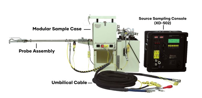
Figure 1-1: Apex Instruments Isokinetic Source Sampling Equipment
Component and Parts:
The Source Sampler Console is the operator’s control station. It monitors gas velocity and temperatures at the sampling location and controls system sampling rate and system temperatures. Housed within the console are the Electrical, Thermocouple, and Vacuum sub-systems.
Electrical Subsystem: The electrical subsystem provides switched power to several circuits, including main power, pump power, manometer zero, timer, probe heater and oven heater. Power rating should be chosen according to your source of electricity. For example, the Apex Instruments XD-502 Sampling Systems can be configured for 120VAC/60Hz or 240VAC/50Hz electrical power.
Thermocouple Subsystem: The thermocouple subsystem displays, measures and provides feedback for the temperature controls that are critical to isokinetic sampling operation. The Apex Instruments thermocouple system consists of Type-K thermocouples, extension wires, male/female connectors, receptacles, a thermocouple selector switch, and a digital temperature display with internal compensating junction. Existing consoles offer automatic and digitally programmable temperature controllers for probe and filter oven heat. The controllers receive temperature feedback signals to maintain temperatures within range of the set point. The thermocouple electrical diagram is presented in the electrical schematic, found in the appropriate operator’s manual.
Vacuum Subsystem: The vacuum pump assembly provides the vacuum for extracting the gas sample from the stack and through the various components of the isokinetic source sampling system. Typically, the vacuum subsystem consists of an external vacuum pump assembly (or internal diaphragm pump), quick-connects, internal fittings, two (2) control valves (coarse and fine), an orifice meter, and a dual-column inclined manometer (or pressure transducer).
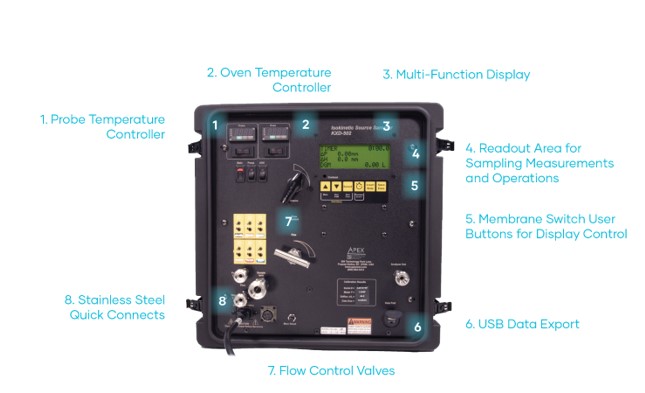
Figure 1-2: Model XD-502 Source Sampler Console Front Panel
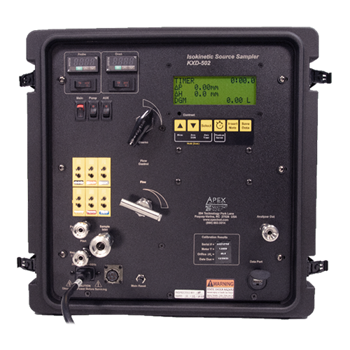
Source Sampler Console Front
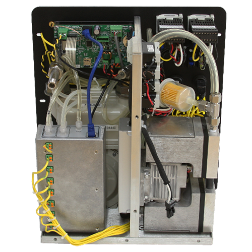
Source Sampler Console Rear
If the console does not have an internal diaphragm pump, it will require an external pump. The External Pump Unit provides the vacuum that draws the sample from the stack. The most common type of pump assembly attaches to the Source Sampler Console via an electrical receptacle and two (2) 1.524 m (5 ft.) hose extensions with 9.525 mm (3/8 in.) quick-connects (configured with a male connector on the pressure side and a female connector on the suction side.
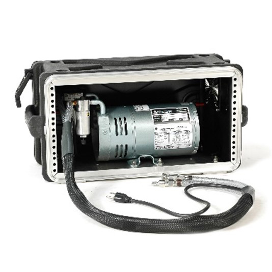
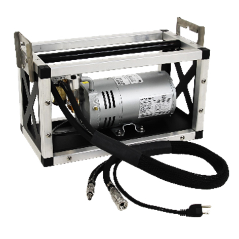
Figure 1-3: XE-0523 (Cased) and E-0523 (Open Frame) Lubricated Vane Vacuum Pump
The main components of a Probe Assembly:
- Probe Liner: 15.9 mm (5/8 in.) OD tubing made from either Borosilicate Glass, Quartz, Stainless Steel, Inconel, or PTFE.
- Probe Heater: Removable rigid tube heater with coiled heating element, electric thermal insulation and thermocouple, with a maximum recommended temperature of 260oC (500oF).
- Probe Sheath: 25.4 mm (1 in.) OD tube with quad-assembly attached that includes a replaceable, modular S-type pitot tube, stack thermocouple and a 1/4 in. OD stainless steel tube to collect gas samples for Orsat analysis.
- Small Parts Kit: Fittings to attach nozzle to Probe Assembly. Fittings include 5/8 in. bored union, nut and ferrules.
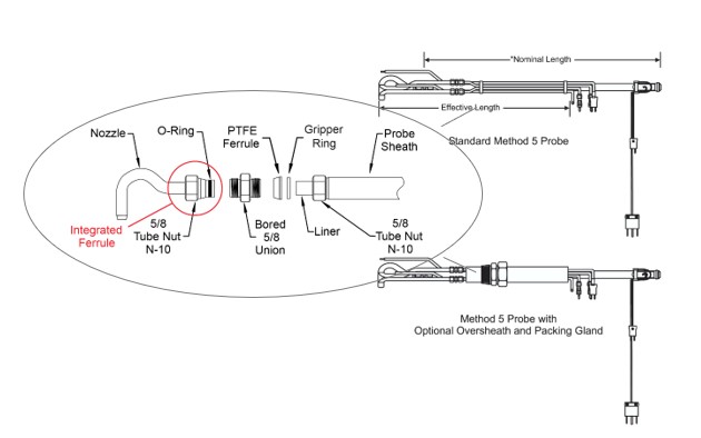
Figure 1-5: Diagrams of Probe Liner Configurations
Probe Liner: Standard Probe Liners are constructed from 5/8 in. OD tubing and have #28 ball joints with an O-ring groove. Available liner materials are borosilicate glass, quartz, stainless steel, Inconel, and PTFE. You will need a ball joint adapter if you have a PTFE liner, straight liner, or liner with integrated nozzles.
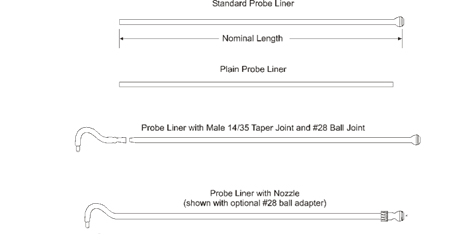
Figure 1-5: Diagrams of Probe Liner Configurations
Probe Heater: For accurate results, the sample temperature should remain in the range of 120ºC ± 5ºC (248ºF ± 9ºF) as it travels through the probe.
Exposure to elevated temperatures can damage the insulation and shorten the life of the heater. The maximum recommended stack exposure temperature for Probe Heaters is 260ºC (500ºF). Partial probe heaters are recommended for temperatures above 260ºC (500ºF).
The Modular Sample Case is used for support, protection, and environmental control of the glassware in the sampling train. The Modular Sample Case consists of an insulated heated filter compartment (Hot Box) and insulated impinger case (Cold Box).
The impinger case (cold box) holds the sampling train impingers in an ice bath so that the stack gas sample is cooled as it passes through the impingers to condense the water vapor. This process allows you to measure stack gas moisture volume, then use that reading to calculate stack gas density.
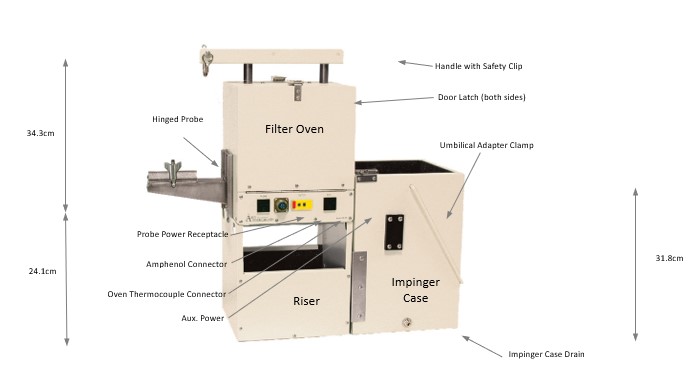
Figure 1-6: Modular Sample Case Components and Accessories
The Umbilical Cable connects the Modular Sample case and Probe Assembly to the Source Sampler Console. The Umbilical Cable typically contains the gas sample and pitot lines, as well as thermocouple and power lines.
- The primary gas sample line (blue, 3/8 in. i.d./12.7 mm (5/8 in. o.d.)) has a male quick-connect on the outlet, at the opposite end, a 12.7 mm (5/8 in.) female quick-connect on the inlet.
- The two (2) pitot lines, (black and white, 6.35 mm (1/4 in.)), have female quick-connects to the Probe Assembly and 6.35 mm (1/4 in.) male quick-connects to the Source Sampler Console. There is an additional gas sample line for Orsat analysis (yellow, 6.35 mm (1/4 in.)), which also can be used as a spare pitot line.
- Multiple thermocouple extension cables for Type-K thermocouples, which terminate with durable full size connectors. The connectors have different diameter round pins to ensure proper polarity and will not fully connect if reversed. Each thermocouple extension wire in the Umbilical Cable is labeled and color coded for temperature measurement of Stack, Probe, Oven (Hot Box), Exit (Cold Box), and Auxiliary (spare).
- The AC power cable (for Filter Oven and Probe Assembly heaters) terminates with a circular, military style connector on each end.
- The Umbilical Adapter connects the outlet of the last impinger to the Umbilical Cable and contains the exit thermocouple. This adapter serves to relieve strain between the Umbilical Cable and the glassware train.
- The body of the circular connector is grounded. A line-up guide is placed on each connector’s end, and the retainer threads should be engaged for good contact.
- The Umbilical Cable is covered with a woven nylon mesh sheath to restrain the cable and reduce friction when moving the cable.
Glassware Sample Train:
The sample glassware train contains the filter holder for collection of particulate matter, glass impingers for absorption of entrained moisture, and connecting glassware pieces.
Below illustrates the glassware of the US EPA Method 5 sampling train. The order in which a typical US EPA Method 5 glassware train is constructed is as follows:
- Cyclone Bypass (GN-1), Optional: Cyclone (GN-2) and Cyclone Flask (GN-3)
- 3 in. O.Z. Filter Assembly (GNFA-3Z). Assembly consists of the Filter Inlet (GN-3S), PTFE Filter Disk or “Frit” (GA-3T), Filter Outlet (GN-3B), and Filter Clamp (GA-3CAZ).
- Double “L” Adapter (GN-8), or alternate GN-8-18K with thermocouple assembly
- 1st Impinger Modified Greenburg-Smith (GT-9A)
- U-Tube (GN-11)
- 2nd Impinger Greenburg-Smith with Orifice (GT-9AO)
- U-Tube (GN-11)
- 3rd Impinger Modified Greenburg-Smith (GT-9A)
- U-Tube (GN-11)
- 4th Impinger Modified Greenburg-Smith (GT-9A)
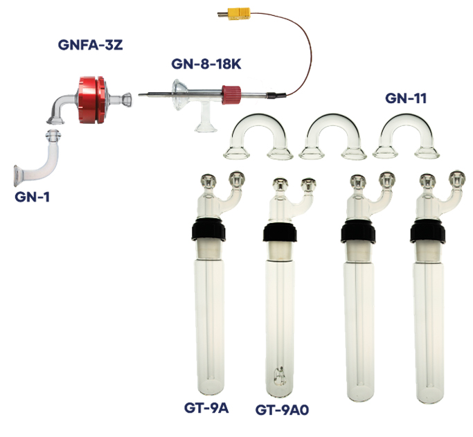
Figure 1-7: Glassware Sampling Train Diagram